|
Dr. CHENG Chun Hung, Director of Research and Technology Development, Logistics and Supply Chain MultiTech R&D Centre and former Associate Professor, Department of Systems Engineering and Engineering Management Introduction
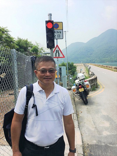
Tai Tam Road (Dam Section) is a declared monument that was constructed more than a century ago. It is a major thoroughfare connecting Chai Wan and Stanley. For years, due to its narrow width of just five metres, traffic deadlock occurred when wide vehicles from both directions entered the section.
The Transport Department (TD) implemented a traffic signal control system on 25 August 2018 such that only traffic from one direction was allowed on the road section at any time. However, the system was considered ineffective and inflexible, due to the fixed traffic signals that did not take account of the prevailing traffic volume.
To improve the traffic situation, TD commissioned the Chinese University of Hong Kong to carry out a study to develop the Smart Control Traffic System (STCS) in January 2018. The STCS collects real-time traffic flow data on each side of the road and automatically allocates the optimal green signal time to reduce the waiting time.
Since the commissioning of the STCS in August 2018, significant improvements have been observed to the traffic conditions in both directions and positive feedback has been received from the community. System Design and Architecture
The STCS is designed to monitor vehicle queue lengths within about 400m of each entrance of the Dam Section, using video-based analysis and vehicle type detection. The STCS has multiple Vehicle Detection Units (VDUs) situated along Tai Tam Road. Each of the units connects to the Control Service Unit (CSU) over the Internet via a mobile network. The Control Service Unit then derives the traffic signal commands and sends them to an on-site traffic signal controller.
The STCS comprises eight VDUs along Tai Tam Road, consisting of 10 cameras attached to eight lamp posts. Queue length is determined based on checkpoints set at about 100m, 200m and 400m from the dam entrances, as well as at the entrances themselves. Images from all ten cameras can be captured and viewed remotely on demand.
Eight of the cameras are placed on the selected lamp posts, arranged to have a downward viewing angle so that the top view of the vehicle can be detected as it passes underneath the lamp post. New vehicle types for detection will be trained using machine learning mechanisms to develop the video analytics capability to detect vehicles from a defined set of vehicle types.
Currently, the project has 16 vehicle types defined for detection: taxi, green minibus, double-decker bus, bicycle, motorcycle, private car, goods van (LGV), Tesla, 5/7 seat car, truck (MGV/LGV), coach, 29-seat minibus, ambulance, fire engine, correctional vehicle and police car.
At the two checkpoints situated at the dam entrances, an additional camera has been placed on the lamp post. These cameras have a view of the road entering the dam to allow TD's designated officers to monitor real-time traffic flow. 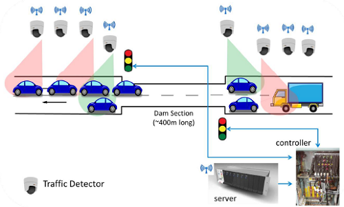
Figure 1. Overview of the STCS
After the VDUs have generated their vehicle type detection results, the information is sent wirelessly to the CSU, where directions on traffic signal timing can be derived and executed. The traffic signal timings are based on the queue lengths on both sides of the dam section. Figure 1 shows an overview of the STCS. System Hardware
The following section describes the hardware needed for the STCS. This includes the hardware for the eight VDUs and the CSU.
A VDU (shown in Figure 2) is a unit for performing on-site vehicle type detection. It is attached to a lamp post, with the camera set at a height of about seven metres and the remaining equipment in a waterproof metal cabinet at the base of the post. The in-cabinet equipment items include a computer for on-site detection processing, a mobile module for sending out detection results, a Power-over-Ethernet (PoE) switch for providing power and video connection to the camera, and a rechargeable battery unit for storing power from the lamp post during evening hours for use during the daytime.
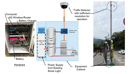
Figure 2. VDU component
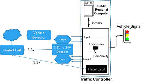
Figure 3. The CSU
The CSU (shown in Figure 3) is situated at the same lamp post as VDU C1. The C1 unit is connected to the traffic controller (QTC). A computer is used as a control unit for sending traffic signal directions after receiving information from the vehicle detector via the cloud. A converter is used to send the directions from the control unit to the QTC by adapting the signal to the correct voltage. System Software
The STCS comprises many components to execute the system, including servers, the cloud, the CSU and VDUs. Each component uses different software to run and execute its programs. Figure 4 shows the interaction of the different hardware components.
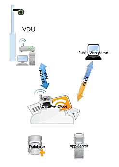
Figure 4. Interaction of hardware components
The CSU uses node.JS to run the system, using Socket.IO and PM2 library dependencies. Device status information is then sent to the cloud via a web socket. The VDUs comprise two smaller units: the Image Capturing Unit and the Vehicle Detector Unit. The Image Capturing Unit monitors image device statuses using node.JS with Socket.IO and PM2 library dependencies. The Vehicle Detector Units are run on Python with the pyyolo library. The two servers for handling web and image processing use the Node.JS system for system execution, while using MySQL for database management. The information is sent to the cloud and delivered. System Behaviour
For the traffic light signal system, the light signals follow a sequence cycling through three different states: North Side Green-South Side Red (North Green), North Side Red-South Side Red (All Red) and North Side Red-South Side Green (South Green). The cycle follows the sequence shown in Figure 5.

Figure 5. The cycle sequence
The traffic signal control mechanism at Tai Tam Road (Dam Section) is similar to conventional traffic signals at junctions, except that the green time can be adjusted dynamically based on the detected traffic conditions, rather than at a fixed time, to reduce vehicle queues. There are several modes that control the traffic signals in various ways.
Standalone Mode refers to the default traffic light programming that is stored in the EPROM chip in the QTC. The periods for red and green time are based on pre-set timings in the program and will not change according to the number of vehicles on the road or the presence of any large vehicles. The STCS has no control over this mode.
Intelligent Mode refers to the program that makes dynamic changes to green time based on the queue length on each side of the dam and the presence of any large vehicles in the queue. The green time is decided by the results from the STCS and aims to reduce the queueing time and chances of traffic deadlock on the dam section.
Intelligent Mode includes a fixed All Red time of 45 seconds to allow sufficient time for vehicles already travelling along the dam section to clear it, and unlimited green time when no vehicles are detected on the opposite side. Comparison of the queue lengths on both sides allocates (15+Ns) or a pre-set amount of green time for the side with the longer queue length and (15+Ns) or a pre-set amount of green time for the other side to better balance the traffic queues. The value of 'Ns' can be fine-tuned to enhance efficiency.
Flexible green time can also be enabled to reduce vehicle waiting time, when there are no more vehicles travelling across the dam section in one direction during green time. By shortening the green time from its maximum value and activating the All Red when the system registers that there are no more cars travelling across the dam section, waiting time is reduced for vehicles waiting to cross the dam in the other direction. The STCS will send an 'OFF' signal for three seconds or more and the 'ON' signal will be sent again after the gap time.
FlexiLink mode refers to when the QTC is being remotely controlled by TD, which can manually control the traffic lights from the Traffic Control Division's Control Centre. This mode has the highest priority and provides immediate control over the timings and statuses of the traffic lights. The STCS has no control over this mode.
Manual Mode can be activated by using a physical key at the lamp post to enable police control of the traffic light signals. The STCS has no control over this mode. Performance of the System
The system in Tai Tam Road (Dam Section) began its pilot operation on 25 August 2018 and has been on trial for six months. Its performance has been satisfactory. On average, with a traditional traffic light, vehicles have to wait 400 seconds for a green light, but with the new traffic light, drivers only need to wait 145 seconds. TD has decided to adopt the new control mechanism for use in Tai Tam Road (Dam Section), with permanent works for this system planned at the site. We believe that we have developed a control mechanism that may be suitable for road use and may be useful in helping solve traffic problems elsewhere in Hong Kong. Acknowledgement
This research has been supported by the Transport Department of the Hong Kong SAR Government. I would like to thank my student Mr. Paul Fung for his video analysis framework for traffic condition detection, and the Transport Department, Highway Departments, Electrical and Mechanical Services Department and Hong Kong Police Force for their advice and assistance during this project. This article was written together with my team at the Logistics and Supply Chain MultiTech R&D Centre.
|